Enable programmable logic support
Goal
- In this tutorial you will
Expand Vivado project from Create minimalist Vivado project for Antelope DPU with support for Programmable Logic
Build bitstream with two UART peripherals connected together
A bit of background
Antelope DPU configuration that you created in Create minimalist Vivado project tutorial has support only for Processing System. Usage of Programmable Logic part of Zynq UltraScale+ requires following capabilities from Processing System side:
Clock for programmable logic
Interrupt lines between Processing System and Programmable Logic
Memory interface between Processing System and Programmable Logic
Zynq UltraScale+ IP block (the same block that you used to configure base settings like DDR memory or I/O pins) configures these options. All Vivado projects describing different “content” of Programmable Logic must use the same base settings. Vivado provides preset mechanism to transfer processing system configuration between projects.
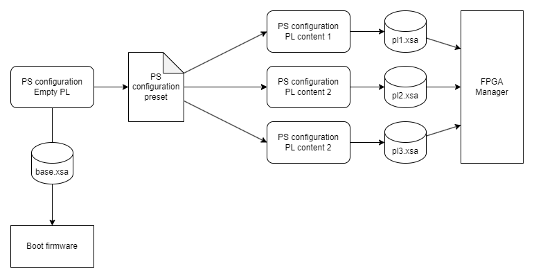
Fig. 1
Multiple Vivado projects sharing Processing System configuration using presets and producing different .xsa files.
Building content for programmable logic involves putting different IP blocks on block design, connecting them together using memory interfaces, interrupts, and clocks. To be usable from Linux distribution, IPs connect to “extension points” provided by Processing System.
Vivado stores content for Programmable Logic in .xsa file in form called bitstream. Using running Linux operating system you can use FPGA Manager to load different bitstreams to Programmable Logic.
Prerequisites
Base Antelope DPU project from Create minimalist Vivado project
Base Yocto project for Antelope DPU from Minimalist Linux distribution
EGSE Host prepared to boot Antelope DPU from network as described in Minimalist Linux distribution
Provided outputs
Following files (Tutorial files) are associated with this tutorial:
Antelope/Zero-to-hero/03 Enable programmable logic support/antelope-minimalistic-with-pl.tcl- Vivado preset for Antelope with enabled PL supportAntelope/Zero-to-hero/03 Enable programmable logic support/antelope-minimalistic-pl-base.xsa- Base XSA file with enabled PL supportAntelope/Zero-to-hero/03 Enable programmable logic support/antelope-double-uart.xsa- Double UART XSA fileAntelope/Zero-to-hero/03 Enable programmable logic support/boot-firmware.bin- Boot firmware for AntelopeAntelope/Zero-to-hero/03 Enable programmable logic support/boot-pins.bin- Boot script for AntelopeAntelope/Zero-to-hero/03 Enable programmable logic support/antelope-minimal-image-antelope.rootfs.cpio.gz.u-boot- Root filesystem for AntelopeAntelope/Zero-to-hero/03 Enable programmable logic support/Image- Linux kernelAntelope/Zero-to-hero/03 Enable programmable logic support/system.dtb- Device tree
Use these files if you want to skip building bitstream or Yocto distribution by yourself.
Enable programmable logic support Vivado
Open Antelope DPU project from Create minimalist Vivado project in Vivado
Use option to open
top_bdblock designCustomize Zynq UltraScale+ block by double-clicking on it
Enable PL to PS interrupts
IRQ0[0-7]Enable PS-PL Master interface
AXI HPM0 FPDEnable PL-PS Slave interfaces
Enable
AXI HPC0 FPDEnable
AXI HPC1 FPDEnable
AXI LPD, set Data Width to 32 bits
Enable Fabric Reset Enable
Set Number of Fabric Resets to 1
Enable PL fabric clock in Output clocks tab
Enable
PL0and set it to 100MHz
In
top_bdblock design connect:maxihpm0_fpd_aclktopl0_clksaxihpc0_fpd_aclktopl0_clksaxihpc1_fpd_aclktopl0_clksaxi_lpd_aclktopl0_clk
At this point block design should contain single IP block with single connection
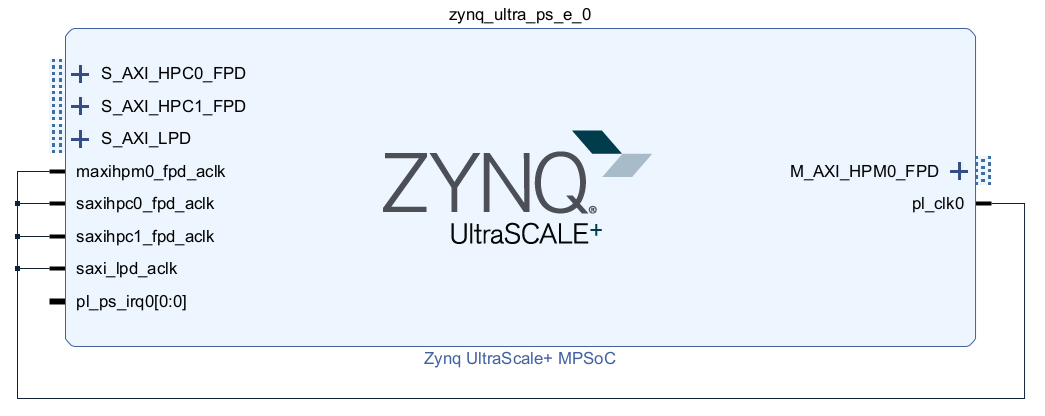
Fig. 2 Block design with Zynq UltraScale+ IP block configured to support Programmable Logic
Open customization of Zynq UltraScale+ IP block and export preset by selecting
Use
antelope-minimalistic-with-plas preset nameSave to
antelope-minimalistic-with-pl.tclfile
Generate bitstream
Export hardware without bitstream. Use
antelope-minimalistic-pl-base.xsafor output file name.
Note
Selected Zynq UltraScale+ configuration covers needs of programmable logic content in this tutorial and next ones.
Create double UART bitstream Vivado
Start Vivado and create new project. In new project wizard select following options:
Project type: RTL Project
Select
Don’t select
Part:
xczu4cg-sfvc784-1L-i
Create top-level block design by using in Flow Navigator. Use
double_uart_bdas name.In block design diagram editor add Zynq UltraScale+ MPSoC IP block.
Start customization of Zynq UltraScale+ MPSoC IP block by double-clicking on it.
Apply previously exported preset by selecting and select
antelope-minimalistic-with-pl.tclfile.
In
double_uart_bdblock design connectmaxihpm0_fpd_aclktopl0_clksaxihpc0_fpd_aclktopl0_clksaxihpc1_fpd_aclktopl0_clksaxi_lpd_aclktopl0_clk
Place two
AXI UartliteIPs on block designCross-connect UARTs by connecting
axu_uartlite1TX toaxu_uartlite0RX and vice versa.Click
Run connection automationand let Vivado instantiate necessary interconnects and resets.Add
ConcatIP blockConnect
doutpin ofConcatblock topl_ps_irqpin of Zynq UltraScale+ blockConnect
interruptpin ofaxi_uartlite0toIn0ofConcatblockConnect
interruptpin ofaxi_uartlite1toIn1ofConcatblockFinal block design should look like this:
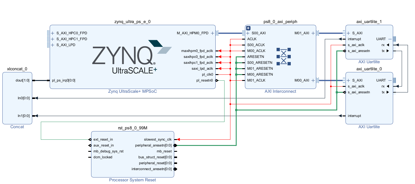
Fig. 3 Block design with double UARTs connected together and available to Processing System
In Sources view select and click in context menu. Use option.
Generate bitstream
Export hardware including bitstream to file
antelope-double-uart.xsa
Enable programmable logic support in boot firmware Yocto
Note
If necessary, re-enable Yocto environment using
machine:~/antelope-linux-1$ source sources/poky/oe-init-build-env ./build
Add
antelope-minimalistic-pl-base.xsatosources/meta-local/recipes-bsp/hdf/external-hdf/directory.Modify
sources/meta-local/recipes-bsp/hdf/external-hdf_%.bbappendto use new XSA file.FILESEXTRAPATHS:prepend := "${THISDIR}/${PN}:" HDF_BASE = "file://" HDF_PATH = "antelope-minimalistic-pl-base.xsa"
Add double UART bitstream to Linux distribution Yocto
Create directory
sources/meta-local/recipes-example/bitstreams/double-uart/and copyantelope-double-uart.xsato it.Create new recipe
sources/meta-local/recipes-example/bitstreams/double-uart.bbthat will install bitstream with double UART.LICENSE = "CLOSED" inherit bitstream SRC_URI += "file://antelope-double-uart.xsa" BITSTREAM_HDF_FILE = "${WORKDIR}/antelope-double-uart.xsa"Create append for
antelope-minimal-imagerecipemachine:~/antelope-linux-1/build$ recipetool newappend ../sources/meta-local/ antelope-minimal-image NOTE: Starting bitbake server... WARNING: The ZynqMP pmu-rom is not enabled, qemu may not be able to emulate a ZynqMP system without it. To enable this you must add 'xilinx' to the LICENSE_FLAGS_ACCEPTED to indicate you accept the software license. Loading cache: 100% |#############################################################################################################################################################################| Time: 0:00:00 Loaded 2030 entries from dependency cache. Parsing recipes: 100% |###########################################################################################################################################################################| Time: 0:00:00 Parsing of 1071 .bb files complete (1069 cached, 2 parsed). 2032 targets, 364 skipped, 0 masked, 0 errors. WARNING: No bb files in default matched BBFILE_PATTERN_meta-kp-classes '^~/antelope-linux-1/sources/meta-kp-classes/meta-kp-classes/' Summary: There was 1 WARNING message. ~/antelope-linux-1/sources/meta-local/recipes-antelope/images/antelope-minimal-image.bbappend createdAdd new packages into Linux image by editing
sources/meta-local/recipes-antelope/images/antelope-minimal-image.bbappendIMAGE_INSTALL += "\ fpga-manager-script \ double-uart \ "Build firmware and image
machine:~/antelope-linux-1/build$ bitbake antelope-allPrepare build artifacts for transfer to EGSE Host
machine:~/antelope-linux-1/build$ mkdir -p ../egse-host-transfer
machine:~/antelope-linux-1/build$ cp build/tmp/deploy/images/antelope/bootbins/boot-firmware.bin ../egse-host-transfer
machine:~/antelope-linux-1/build$ cp build/tmp/deploy/images/antelope/u-boot-scripts/boot-script-pins/boot-pins.scr ../egse-host-transfer
machine:~/antelope-linux-1/build$ cp build/tmp/deploy/images/antelope/system.dtb ../egse-host-transfer
machine:~/antelope-linux-1/build$ cp build/tmp/deploy/images/antelope/Image ../egse-host-transfer
machine:~/antelope-linux-1/build$ cp build/tmp/deploy/images/antelope/antelope-minimal-image-antelope.rootfs.cpio.gz.u-boot ../egse-host-transfer
Transfer content of
egse-host-transferdirectory to EGSE Host and place it in/var/tftp/tutorialdirectory
Loading double UART bitstream on DPU EGSE Host
Verify that all necessary artifacts are present on EGSE Host:
customer@egse-host:~$ ls -lh /var/tftp/tutorial
total 30M
-rw-rw-r-- 1 customer customer  22M Jul 10 11:14 Image
-rw-rw-r-- 1 customer customer 1.6M Jul 10 11:14 boot-firmware.bin
-rw-rw-r-- 1 customer customer 2.8K Jul 10 11:14 boot-pins.scr
-rw-rw-r-- 1 customer customer  16M Jul 10 11:14 antelope-minimal-image-antelope.rootfs.cpio.gz.u-boot
-rw-rw-r-- 1 customer customer  37K Jul 10 11:14 system.dtb
Note
Exact file size might differ a bit but they should be in the same range (for example
antelope-minimal-image-antelope.rootfs.cpio.gz.u-bootshall be about ~16MB)Ensure that Antelope is powered off
customer@egse-host:~$ sml power off
Powering off...Success
Power on Antelope
customer@egse-host:~$ sml power on
Powering on...Success
Power on DPU
customer@egse-host:~$ sml dpu power on
Powering on...Success
Write boot firmware to DPU boot flash
customer@egse-host:~$ sml dpu boot-flash write 0 /var/tftp/tutorial/boot-firmware.bin
Uploading   ━━━━━━━━━━━━━━━━━━━━━━━━━━━━━━━━━━━━━━━━ 100% 0:00:00 43.1 MB/s
Erasing     ━━━━━━━━━━━━━━━━━━━━━━━━━━━━━━━━━━━━━━━━ 100% 0:00:00 383.9 kB/s
Programming ━━━━━━━━━━━━━━━━━━━━━━━━━━━━━━━━━━━━━━━━ 100% 0:00:00 13.1 kB/s
Write U-Boot boot script to DPU boot flash
customer@egse-host:~$ sml dpu boot-flash write 0x4E0000 /var/tftp/tutorial/boot-pins.scr
Uploading   ━━━━━━━━━━━━━━━━━━━━━━━━━━━━━━━━━━━━━━━━ 100% 0:00:00 ?
Erasing     ━━━━━━━━━━━━━━━━━━━━━━━━━━━━━━━━━━━━━━━━ 100% 0:00:00 ?
Programming ━━━━━━━━━━━━━━━━━━━━━━━━━━━━━━━━━━━━━━━━ 100% 0:00:00 63.9 MB/s
Open second SSH connection to EGSE Host and start
minicomto observe boot processcustomer@egse-host:~$ minicom -D /dev/sml/antelope-dpu-uart Leave this terminal open and get back to SSH connection used in previous steps.Release DPU from reset
customer@egse-host:~$ sml dpu reset off 7DPU boot process should be visible in
minicomterminalLog in to DPU using
rootuserantelope login: root root@antelope:~#Load double UART bitstream
    root@antelope:~# fpgautil -o /lib/firmware/double-uart/overlay.dtbo
    [   17.334051] fpga_manager fpga0: writing double-uart/bitstream.bit.bin to Xilinx ZynqMP FPGA Manager
    [   17.478795] OF: overlay: WARNING: memory leak will occur if overlay removed, property: /fpga-full/firmware-name
    [   17.488941] OF: overlay: WARNING: memory leak will occur if overlay removed, property: /fpga-full/resets
    [   17.498582] OF: overlay: WARNING: memory leak will occur if overlay removed, property: /__symbols__/afi0
    [   17.508081] OF: overlay: WARNING: memory leak will occur if overlay removed, property: /__symbols__/axi_uartlite_0
    [   17.518445] OF: overlay: WARNING: memory leak will occur if overlay removed, property: /__symbols__/axi_uartlite_1
    [   17.532846] a0000000.serial: ttyUL0 at MMIO 0xa0000000 (irq = 45, base_baud = 0) is a uartlite
    [   17.543564] uartlite a0000000.serial: Runtime PM usage count underflow!
    [   17.553041] a0010000.serial: ttyUL1 at MMIO 0xa0010000 (irq = 46, base_baud = 0) is a uartlite
    [   17.563853] uartlite a0010000.serial: Runtime PM usage count underflow!
    root@antelope:~#

.. note:: Despite warnings UARTs in bitstream will still function correctly
Verify presence of two new UART devices
root@antelope:~# ls -l /dev/ttyUL*
crw-rw----    1 root     dialout   204, 187 Sep 20 11:23 /dev/ttyUL0
crw-rw----    1 root     dialout   204, 188 Sep 20 11:23 /dev/ttyUL1
Start receiving data from
/dev/ttyUL0in backgroundroot@antelope:~# cat /dev/ttyUL0 & ``cat`` process will be running in background allowing you to enter another command in the same terminal. Output from ``cat`` (data received from UART) and your commands will mix in terminal.Write something to second UART:
    root@antelope:~# echo "Hello from UART1" > /dev/ttyUL1
    Hello from UART1
    root@antelope:~#

Text ``Hello from UART1`` is coming from ``cat`` running in background.
Summary
In this tutorial, you enabled usage of Programmable Logic part of Zynq UltraScale+ device. As an example, you added bitstream with two UARTs connected together. After rebuilding Yocto project, you used FPGA Manager to load bitstream dynamically and used newly added devices.